 |
|||||||
 |
 |
||||||
 |
|||||||
 |
|||||||
|
|||||||
|
|
||||||
|
|||||||
|
|||||||
|
Project Blade RunnerPage 6Each hammer required a small hand-drilled hole to allow placement of a tiny spring in it, as well as a hole for the brass rod that provides the pivot for the actuating lever to swing on. I then worked on the hammer return spring assembly.
The stock Bulldog hammer spring runs on a special ball ended
rod that traps the spring between the ball end (just below the hammer)
and a rectangular washer that is loaded against the grip sub-frame at
the lower end. These rods are no longer available from the From a trip to the local hobby store, I managed to find a suitable small ball and socket rod end assembly. This particular part is used in RC planes and is made to screw onto 4/40 threaded rod. I cut some threaded rod to the appropriate length and then sheathed the threads with a section of brass tubing to eliminate spring hang-up on the thread peaks. I finished off the assembly using a nylon washer that fit over the brass tubing and a 4/40 nut to fasten it all together. The end result works flawlessly. The trigger also needed major modifications to
be functional as a polyurethane casting. The original steel trigger
on the Bulldog has very thin sides with a deep slot right through the
middle where a scissor-shaped return spring resides. These thin
walls would never work cast in plastic, so I filled the recess and designed
the new trigger to use a straight coil spring. This effort required
four reorders from a spring company to get a workably sized spring.
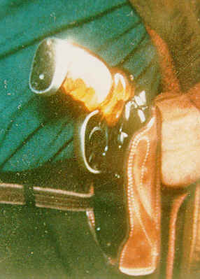
From a study of many film shots, the pistol grips seem to have been a translucent amber material. Working with fiberglass resin and various dyes, I experimented until I had just the right color. After sanding and smoothing the grips, the undersides were painted silver to mask the grip frame internals, followed by painting with a coat of Krylon® Crystal Clear enamel. The specialized side rod “pointer” component on the blaster needed a mounting system, so I cut a slot into it and then glued a strip of plastic into the slot. The side rod could now be glued directly to the left side cover to match the prop gun. The rear section of the side rod was removed and glued into a mold box to allow separate casting and maximum retention of its knurling details. Included in this mold box was the cylinder thumb release latch, the Steyr safety latch, and the little knob from the front of the right side cylinder cover plate. As it seems that the rather large but shallow slot-head
binding screw used on the right side cover is apparently no longer available
(or at least is uncommon), I cut down a readily available binding head
screw, which is similar but
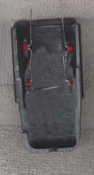
For the ammo housing, careful placement and drilling of the two small holes on the left side was required in order to match the original prop. As suspected, we later confirmed through our interviews with the original prop designer that these access holes were added to reach the on/off switch for the LEDs. This ammo housing was then cut and fitted so that one side overlapped the right side cylinder cover the same way the original prop did, as evident in the stunt copies. Like the receiver on top,
the ammo housing also ended up with a deep round milled cut to fit under
the new revolver barrel. I
also incorporated a slot and bar locking system for the housing and
its ammo clip. In order
to fit, the clip had to be cut down and trimmed to include the LEDs,
battery holder, and electrical switch within the housing. Interestingly, the original Steyr bolt lever is straight, unlike the lever observable on the stunt prop, which is curved to match the contour of the right side cover. The Steyr cocking lever had to be heated and bent inward to match the this contour. Presumably, the original propmaker had to do the same. The Steyr bolt rear cap was trimmed and then filled in to fit onto the rear of the bolt. With the working parts of the prototype completed, we were now ready to cast all of the converted and modified components to make the final model. Thus, working molds were made using these newly created master parts. Part 2
|


 with a slightly taller profile, for use as a pattern to mold.