Project: Blade Runner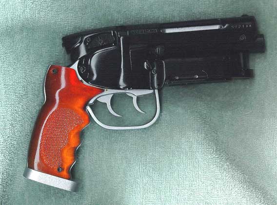
Part Two, Assembly.
By Richard A. Coyle
In Part One I outlined all of the modifications needed to create the masters
for this intricate model.
Those of you who have done some prop casting will realize
that I have left out many details about mold making, such as positioning of pour
points and air vents, parting lines, etc.
The thrust of this initial article series is to relate the
making of the blaster model from a research, engineering, and fabrication
standpoint. To properly cover all
of these basic mold making details
could take as many pages as the first two articles combined.
Besides, it is a well covered
subject in many other sources, so I have decided to gloss over it here.
Perhaps some time in the near future I will do an article
series on making molds and casts in the context of creating this type of model.
Meanwhile, back to our saga:
With the new molds ready, I cast an initial run of
four sets of every component. This was to insure that I would finish with at
least two completed models, one for Phil and one for me, with a selection of
spare parts from whatever was left over.
After casting the raw parts, all flash is trimmed (the
little extra plastic lip that typically finds its way into the parting
lines of a mold), and all pour
points and vents are dressed.
Next, all of the various holes must be drilled, and those
that will have screws used to fasten parts are tapped to the appropriate thread.
Each model is then sanded with 300 grit sand paper,
followed by 400 grit, and finally red Scotch-Brite® pads to a smooth finish.
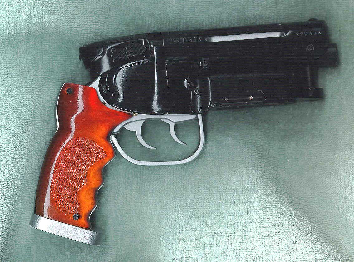
I test fit the grips and sand them to fit.
The
models can now be dry assembled to check for proper fit and any correction
requirements. Any problems are fixed and the parts refitted.
Once
I am satisfied that everything fits and functions well, all of the components
are disassembled and mounted on wooden posts for painting.
Each
and every part gets a base coat of primer, two to three coats of enamel in the
appropriate color, and then three finish coats of clear enamel.
Turning to the lathe, I then section two brass
rods to make the trigger pins, a piece of brass tubing for the hammer pin, five
pieces of brass tubing for the cylinder rod, and one piece of brass tubing for
the hammer spring assembly for each model.
The small knob on the side cover, as well as the main body and end of the
side rods, are then center drilled with the lathe.
The next part to be machined is the cylinder, which first necessitated
making a set of soft jaws to perform the lathe work without damaging the parts.
Once chucked, I face off the bearing surface, leaving a small, raised washer-like
projection on the front end of each cylinder.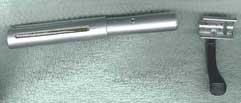
The
next step was to turn down an aluminum tube to the same outside diameter of
the bolt, and then bore it to the inside diamet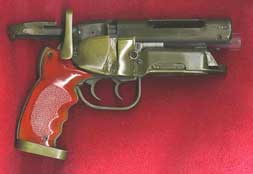 er
of the bolts necked-down end to provide for the rotation inside the receiver.
er
of the bolts necked-down end to provide for the rotation inside the receiver.
Again using the lathe, I turn down the ends of
a 3/4-inch acrylic tube for the barrel and then crown the business end to reproduce
a true gun barrel appearance.