 The main frame is, of course, the Bulldog with its trigger guard and pistol
grip subframe removed. To replace the grip frame I used an older
stunt casting to section out a frame that matched the outline of the blaster
grips. The master pattern grips were dissected from one of the best
stunt prop castings I had.
The main frame is, of course, the Bulldog with its trigger guard and pistol
grip subframe removed. To replace the grip frame I used an older
stunt casting to section out a frame that matched the outline of the blaster
grips. The master pattern grips were dissected from one of the best
stunt prop castings I had. 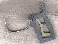
After cutting away most of the Bulldogs subframe,
I grafted the portion containing the hammer spring rest into the interior
of the protoype's pattern grip frame. This gave me the perfectly
proportioned mounting part for the new blasters hammer spring.
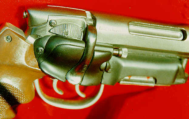
Next came the trigger guard. This step required
cannibalizing two guards from castings of the stunt props, which had
to be enlarged in order to fit the real Bulldog frame. The guard
had to be sectioned in the middle and additional material grafted onto
the end.
Noting that no screw is visible on the exterior
of the trigger guard on any stunt castings, and also that the rear of
the trigger seems to roll up into the frame by the grips, I engineered
a slot and groove mounting system. Observing that the front of
the trigger guard can pass directly over the cylinder swing arm screw,
I thought, why not use it to do both? So I did. And I
suspect thats exactly what the original propmaker did as well. 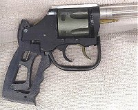
Returning to the stunt prop, I compared the triggers
and verified that the rear trigger was identical to the Bulldog, with
its characteristic grooves and profile, so this is in fact what was
used on the hero prop. Interestingly, the front one was exactly
the same -- just cut down slightly to fit into the Bulldog's frame where
the front part of the subframe used to mount.
Concluding (with the mindset of the propmaker)
that I would probably want to avoid drilling into a chromoly steel gun
frame, I quickly found I could use the front subframe pin as the new
trigger bushing mount. Next came the new custom pistol grip frame.
Once again figuring that I would not want to drill into the steel frame,
I milled the new grip frame to fit into the Bulldog's frame in the same
way the Bulldog's subframe previously mounted in the rear.
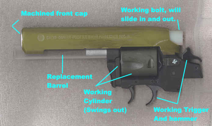
At this point it was time to begin fitting the Steyr
receiver onto the Bulldog frame. From the stunt prop it was obvious
that two 4/40 Allen screws were used to hold the front of the Steyr
receiver to the firing barrel. However,  there are no visible screws that line up with the Steyr and the Bulldog
frame underneath.
there are no visible screws that line up with the Steyr and the Bulldog
frame underneath.
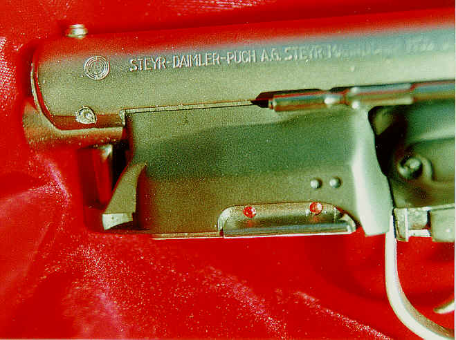
With the center cut away, there was no easy way
to mount the Steyr receiver onto the Bulldog , and it is not readily
apparent how the propmaker originally secured the rear of the receiver
to the revolver frame, either. The only visible rearward screw
is the one just above and to the rear of the safety, but on the stunt
castings this screw is too high and could only have screwed into the
rear bolt cap. In fact, I believe this is exactly what that screw
was used for to hold the rear bolt cap (and thus the bolt) in place.
The only option was to engineer a new rear mount for the Steyr. 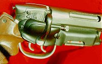
After careful consideration, I settled on a slot
and rail design for the mount. I cut two slots into the inside
walls of the Steyr receiver (one on each side) and then glued two corresponding
rectangular rails onto the Bulldog frame. This may well have been
done by the original propmaker, by either pinning or soldering
two like metal bars onto the steel revolver frame of the hero prop.
This design made the Steyr receiver very secure
as well as easy to remove.