|
|||||||
 |
 |
||||||
 |
|||||||
 |
|||||||
|
|||||||
|
|
||||||
|
|||||||
|
|||||||
|
Project Blade Runner Part 2Page 3
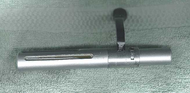
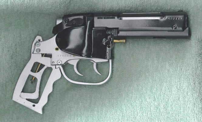
The bolt assembly is then inserted into the receiver, and the longer set screw in the Steyr receiver is screwed in to engage the travel slot in the top of the bolt. Next, the entire Steyr receiver assembly is slid onto the bars cast into the Bulldog's frame using the slot and rail mounts. The assembly is then fastened to the Bulldog barrel at the front using two 4/40 Allen screws inserted through the milled notches in the receiver.
For
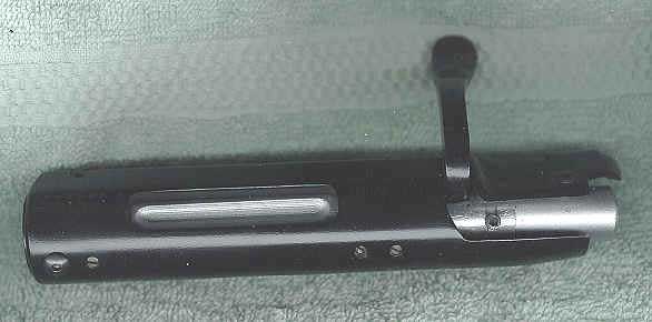
attachment of the right side knob, I thread a short piece of 4/40 rod into the
knob and then mount this to the front edge of the right side cover into a
previously prepared hole. Once
the cover is fitted and the cocking lever and bolt action satisfactorily tested,
I can finally mount the Steyr bolt cap casting using a small 4/40 button head
Allen screw exactly like the original prop. Once
the cover is fitted and the cocking lever and bolt action satisfactorily tested,
I can finally mount the Steyr bolt cap casting using a small 4/40 button The
cylinder is then mounted to the swing arm for final assembly.
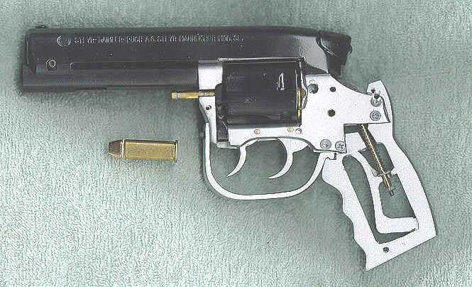
To give the model actual rounds for the cylinder, I manufactured
safe ammo by pressing hollow point bullets into primerless cartridges.
These rounds are now loaded into the cylinder,
which is swung closed to engage the locking rod into the Bulldog frame.
Things are really shaping up at this point. To mount the side rod, its knurled end cap is first glued on, and then the entire rod is glued to the left side cover. The left side cover with the rod can now be mounted directly onto the swing arm with two 4/40 Allen screws Table Of Contents
|