The Classic Star Trek Phasers
Part two.. The 2nd Season Page 5
By Richard A. Coyle
 Sadly,
this effort and cleverness was not carried through to the system to make these
handles removable. They settled on using a plain simple old two prong twist
locking electrical extension cord plug and socket. This was so "household"
and everyday familiar that I am sure it is why we never see anyone unlock and
change the power pack. (Having tried to make this feature, I understand how
hard this simple trick is, here is nothing I could find that would work either.)
Sadly,
this effort and cleverness was not carried through to the system to make these
handles removable. They settled on using a plain simple old two prong twist
locking electrical extension cord plug and socket. This was so "household"
and everyday familiar that I am sure it is why we never see anyone unlock and
change the power pack. (Having tried to make this feature, I understand how
hard this simple trick is, here is nothing I could find that would work either.)
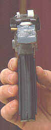
 While
we are talking about these special features let's go over them. The working
features of the pistol body were: the rotating ring (discussed in the beginning
of this article). Then there was a twist knob on the side of the pistol body
with the five settings. Of course, there was a working trigger which operated
the tip light and the feature that moved the tip in and out.
While
we are talking about these special features let's go over them. The working
features of the pistol body were: the rotating ring (discussed in the beginning
of this article). Then there was a twist knob on the side of the pistol body
with the five settings. Of course, there was a working trigger which operated
the tip light and the feature that moved the tip in and out.
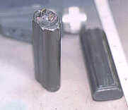
 What happened was that as the phaser one is loaded into the pistol body, the
front of the phaser engages a pocket that it has to push forward. This socket
connects to the tip so that when the socket is pushed forward, the tip telescopes
out of the muzzle. When the phaser one is removed, this action would, of course,
retract the tip. As a point of interest to nitpickers and fans of bloopers,
there are a couple of scenes where you can see were this part failed to engage
or failed to hold and the tip pocket has slipped under the phaser one and the
tip has withdrawn into the muzzle. Check for this in a scene from "The
Conscience of the King" and other episodes.
What happened was that as the phaser one is loaded into the pistol body, the
front of the phaser engages a pocket that it has to push forward. This socket
connects to the tip so that when the socket is pushed forward, the tip telescopes
out of the muzzle. When the phaser one is removed, this action would, of course,
retract the tip. As a point of interest to nitpickers and fans of bloopers,
there are a couple of scenes where you can see were this part failed to engage
or failed to hold and the tip pocket has slipped under the phaser one and the
tip has withdrawn into the muzzle. Check for this in a scene from "The
Conscience of the King" and other episodes.
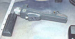
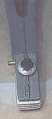
 Next
moving rearward and up behind the phaser one but still on the left side of the
main pistol body, we come to the little brass rod that sticks out from the side.
When I first watched the shows, I remembered Captain Kirk telling the crew to
lock the phasers on stun. I believed that was what this button was for, to lock
the setting knob into place. I was wrong.
Next
moving rearward and up behind the phaser one but still on the left side of the
main pistol body, we come to the little brass rod that sticks out from the side.
When I first watched the shows, I remembered Captain Kirk telling the crew to
lock the phasers on stun. I believed that was what this button was for, to lock
the setting knob into place. I was wrong.
 In the real world, it was the lock release for the removable phaser one. The
others simply had the cast phaser one glued into the pistol body and dummy brass
rods which were inoperative.
In the real world, it was the lock release for the removable phaser one. The
others simply had the cast phaser one glued into the pistol body and dummy brass
rods which were inoperative.
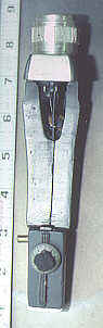
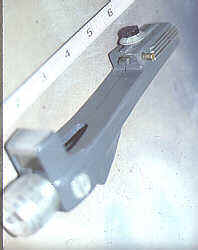
 The next stop is up on top at the rear we find the pistol setting knob. On the
these later models they found a great little knob with markings and numbers.
It had a aluminum cone shaped ring with the numbers and, with a little cutting
and work, a small knob to twist it with. These came off radio gear ten turn
knobs and so costly, so a few were replaced with simple machined copies.
The next stop is up on top at the rear we find the pistol setting knob. On the
these later models they found a great little knob with markings and numbers.
It had a aluminum cone shaped ring with the numbers and, with a little cutting
and work, a small knob to twist it with. These came off radio gear ten turn
knobs and so costly, so a few were replaced with simple machined copies.
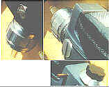
 The final detail to describe is the rear radiator section. On the back ground
far shot models there was a little detailing most that consisted of cutting
six lines into the side, back and around to the other side. Then painted them
silver.
The final detail to describe is the rear radiator section. On the back ground
far shot models there was a little detailing most that consisted of cutting
six lines into the side, back and around to the other side. Then painted them
silver.
On the "heros" used for the inserts and close-ups there
was a hand made radiator made up of four and only four aluminum plates sandwiched
with three smoked plastic plates for spacers.